SBeXpress Module Z
SBeXpress BIM (Formwork) Module
The BIM (Formwork) module replaces fragile "plain AutoCAD" workflows with intelligent, level‑aware formwork objects. Instead of hundreds of disconnected lines, hatches and texts, you work with walls, slabs, openings and grids that know their storey, style and labels – and update themselves when geometry changes.
What problem does the BIM module solve?
Traditional formwork drafting in AutoCAD means manually keeping hundreds of primitives in sync: outlines, hatches, diagonals, labels and blocks all need separate updates whenever something changes. This is slow, brittle, and error‑prone – especially on projects with many levels.
- Labels and hatches go out of sync when geometry moves.
- Filtering by level or generating elevations requires manual work.
- Global restyling (line types, fills, labels) is practically impossible.
How the BIM module changes the workflow
- Formwork is drawn with intelligent objects (walls, slabs, openings, grids).
- Each object is style‑driven: one style controls boundary, fill, labels and blocks.
- Objects are level‑aware: they know which storey they belong to and follow level visibility rules.
- Labels are linked to geometry and properties, so they update when you edit the object.
Scope of the BIM (Formwork) module
The module focuses on formwork plans: what gets cast, on which level, with which openings and recesses. It provides a set of object families, all based on the same underlying technology, so formwork plans, elevations and tables stay consistent.
Slab‑related objects
For modelling cast‑in‑place slabs.
- • Slab contours (plan)
- • Slab openings
- • Slab recesses (upper / lower / both)
Wall‑related objects
For walls and their openings, including wall views for elevation drawings.
- • Wall contours
- • Wall openings
- • Grooves / slots
- • Wall views (elevations)
Columns and prefabricated slabs
For vertical and prefabricated elements shown on the formwork plan.
- • Column (pillar) objects
- • Prefabricated slab objects
Foundation / base objects
For footings and base slabs, including level discs and foundation‑specific labels.
These are the only objects that can host level marker discs.
General surface objects
For bedding, hatching and other filled areas that need to be attached to levels and styles.
Useful for screeds, insulation zones and other surface‑based indications.
Generic contour objects
The most general object type – a contour that can represent many element categories depending on its assigned type and style.
Ideal for custom shapes where you still want style‑driven rendering and labelling.
Core concept: the SurfaceContour object
Almost all BIM module objects are built on a single, powerful building block: SurfaceContour. It is a closed polyline‑like boundary with additional metadata and style links that control how the object looks, how it is labelled, and how it participates in levels and elevations.
Why SurfaceContour instead of manual drafting?
- You move, copy or delete a single object, not a bundle of lines and hatches.
- Interior drawing (diagonals, hatches, blocks) automatically follows the boundary when you edit grips.
- Global restyling is a matter of changing ContourStyle, not redrawing.
- Labels and consignment blocks are linked to properties – they update when geometry or metadata changes.
Key SurfaceContour properties
- • Lower and upper planes (or plane + height)
- • Height computed from plane + thickness where applicable
- • Level / storey assignment
- • Contour type (wall, slab, opening, recess, generic, …)
- • ContourStyle (boundary + fill + blocks + labels)
- • Mark / Tag fields usable in labels (e.g. for openings)
- • Note / Comment fields for additional information
Creating contour‑based objects
Every workflow starts by selecting the desired Contour Type (wall, slab, opening, recess, generic…) from the BIM toolbar. This pulls default styles from the "Default objects" configuration. You then define the boundary using one of several methods.
Definition methods
- • Click‑point polygon (straight segments)
- • Drawing a polyline (straight + arc segments)
- • Two opposite points (rectangle → contour)
- • Generate from existing line / arc / polyline elements
- • Generate from a hatch boundary
Geometry quality requirements
For "generate from elements" to work, selected segments must form one continuous, closed chain. Gaps, overshoots and near‑misses prevent contour creation and should be fixed first (or repaired later with dedicated tools).
Command quick reference
- contcrlgen – contour by click‑points
- contcrgen – contour by drawing polyline
- crfundcv – contour from selected elements
- hatchcv – contour from hatch
- contsub2 – rectangle (2 points) → contour
Walls – creation, tools and elevations
Wall objects are specialized contours with additional tooling for openings, views and elevations. They can be created directly as walls or converted from existing geometry such as imported DWGs.
Wall creation and editing utilities
- From linework – convert selected lines/arcs/polylines into wall objects using current defaults.
- From hatches – generate walls from hatch boundaries, then move them into position.
- From ArchiCAD DWG – detect ArchiCAD‑like blocks and convert them into walls in a cyclic pick‑and‑convert workflow.
- Union closed contours – merge overlapping contour objects into a single closed wall contour.
- Join collinear walls + insert opening (punioopen) – join two walls and automatically create an opening between them.
- Split multi‑vertex walls – split a wall at a chosen vertex to clean up elevations.
- Copy skeleton objects – copy simplified formwork elements into elevation drawings for reinforcement detailing.
Wall elevations and properties
- Generate a single wall elevation from a selected wall, or all wall elevations for the drawing.
- Elevations include the wall side view, slab sections above/below, level markers and a context copy.
- The context bounding box is configured in General settings → Formwork → Wall elevation generation.
- A horizontal‑rotation option controls whether elevations are placed uniformly or follow the wall's view arrow direction.
Notable wall properties
- • Mark and user property code (for labels and tables)
- • Note / Comment fields
- • ContourStyle (including "next level" representation)
- • Slab‑relative wall height option
- • Brick wall flag and level assignment
- • Associated slab detection/override
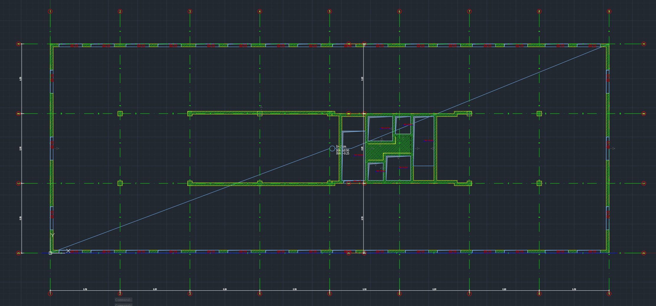
Slabs – parameters, slopes and sections
Slabs use the same contour technology but have slab‑specific parameters such as thickness, material grades and computed quantities. You can define flat, sloped and variable‑thickness slabs and generate sections from them.
Slab contour types
- • Slab plan
- • Slab opening
- • Slab recess (upper / lower / both)
Default styles for each type are configured in the "Default objects" settings.
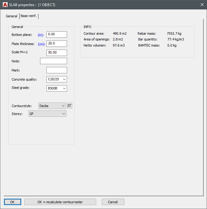
Key slab parameters
- • Lower plane and slab thickness
- • Computed upper plane
- • Mark / Note fields used in format‑string labels
- • Concrete and rebar grades (with sensible defaults)
- • Info panel with area, volume and reinforcement mass estimates
Openings and recesses have similar properties plus recess depth and flags for upper / lower recess.
Slopes and sections
- LEVELDEF – define a sloped slab by three points, each with elevation and thickness.
- LEVELDEF2 – define slopes by a vector and top/bottom slope percentages.
- Height labels can be placed to report computed elevations at arbitrary points.
- crslabs – generate slab sections along a cutting line; style‑driven and annotated with levels.
Note: generated sections are not associative – if slab geometry changes, regenerate or update sections manually.
Create slabs from existing walls
With mkslab you can generate a slab that "covers" selected walls. The resulting slab belongs to the same level as the walls, its lower plane is taken from the wall tops, and its thickness is pulled from global formwork settings for that level.
Generating wall views, and cross-sections
Once the model is sufficient, you can quickly generate wall views, and cross-sections from objects.
Wall views
- • set the style of the walls, and openings in the view
- • generate one wall views, or all wall views
Cross-sections
- • Choose the style of the cross-sections
- • Generate cross section of the whole building by giving an axis line
BIMTools
SBeXpress BIMTools is a WPF desktop application (.NET 6) for visualizing, analyzing, and exchanging BIM data using IFC (Industry Foundation Classes) and DXF.
- Load and visualize IFC models — open IFC files and show the 3D building hierarchy (storeys, walls, slabs, beams, columns, openings, reinforcement).
- Navigate and filter — tree view of the building, filter by element type, toggle visibility, inspect properties.
- Cutting planes and cross-sections — create cutting planes (interactive or by storey), generate and view 2D cross-sections.
- Export and interchange — save IFC (full or selection); export reinforcement and cross-sections to DXF; import DXF and convert to IFC (e.g. walls, slabs, beams, openings).
- Integrated with SBeXpress: Importing / Exporting can be triggered from the SBeXpress interface. For example when you export your model to IFC, SBeXpress will generate a dxf, which will be then processed by BIMTools, and an IFC file will be generated. BIMTools then starts automatically with the new IFC file open in the 3D view.
Level / storey management (STAGES)
Level management is central to how the BIM module works. Most objects carry a Level property and follow visibility rules driven by the STAGES panel and general settings.
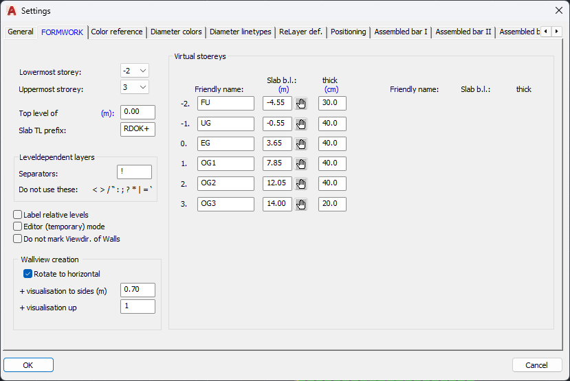
Defining levels
- • Configure number of levels and base slab elevations.
- • Define virtual levels by lower planes and thicknesses.
- • Assign human‑friendly level names (e.g. "Basement").
STAGES panel
- • Choose the current level; new objects are created there.
- • Toggle per‑level visibility with one click.
- • Quickly switch level combinations and regenerate the view.
Level‑related tools
- elestage – adjust Z without changing level.
- cpystage – copy objects to another level with Z increment.
- noreinf – mark objects to be hidden on reinforcement plans.
- Layout generation per level – automatically creates layouts like "Basement formwork".
Level marker discs on foundations
Level discs are special annotation objects that can only be placed on foundation/base objects. They combine a block (arrow/disc) with a level label style and are typically used to show finished level elevations on footings and base slabs.
- • Full level disc with top arrow block
- • Half level disc with bottom arrow block
- • Two‑part label where the second part can hold suffixes (e.g. "mBf.")
Important: if foundation plane heights change later, existing discs do not update automatically – adjust values in the disc properties.
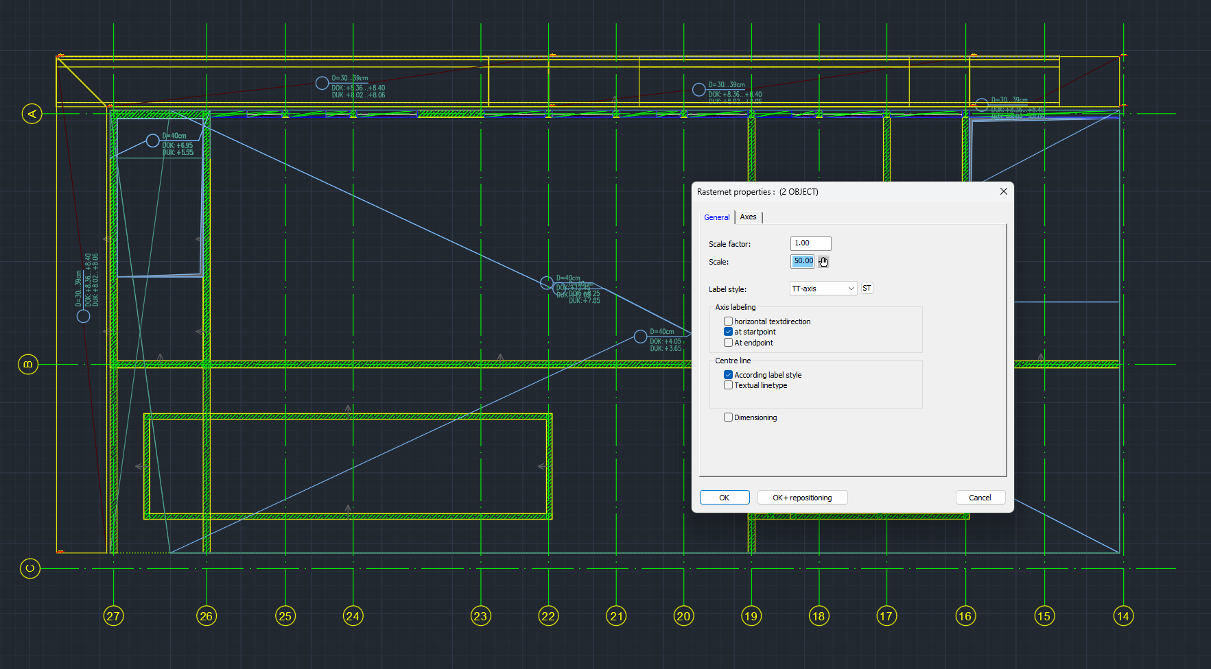
Grid / axis object
Intelligent composite object
The grid/axis object groups axis lines, bubbles and labels into a single editable unit. Spacing, labels and visual style are parameter‑driven and can be updated after creation without re‑drawing.
- • Adjustable scale and drawing scale
- • Label styles for axis bubbles and dimensions
- • Optional intelligent dimensions between axes
Axis marks and directions
You can define axis marks, numbering directions and main‑axis angles so that grids follow the project's conventions (e.g. letters horizontally, numbers vertically).
- • Horizontal/vertical text direction options
- • Label at start/end of each axis
- • Axis repositioning while keeping labels consistent
Existing plain AutoCAD grids can be converted into grid objects with the craster command, preserving geometry while gaining parametric control.